
Isolated Multiple Output Flyback Converter Design Using TL494 SrivatsaRaghunath ABSTRACT The TL494 is one of the earliest pulse-width-modulation PWM controllers used in switched mode power supplies.ĭiscover and save your own Pins on Pinterest. The design requirements of the ENZI dictate the specifications of a DCAC power inverter that this project will endeavor to produce.Ĭonverter 12 Vdc To 230 Vac Or Inverter Power Supply Circuits. This TL494 buck converter circuit is for demonstration purposes only hence there is no protection circuit is added in the output section of the circuit An output protection circuit must be added to protect the load circuit. TL494 Circuits TL494 Projects TL494 integrated two amplifiers adjustable oscillator dead time control DTC comparator pulse steering control flip-flop a 5V precision regulator and output control circuits TL494 device can work as push-pull or single output 02V-80V 0-10A Adjustable Switched Mode Power Supply gevv 20200702. TL494 Block Diagram SLVA001EDecember 2003Revised September 2011 Designing Switching Voltage Regulators.
INVERTER DESIGN SCHEMATIC HOW TO
In this episode Ill show you how to make your own 3kW inverter with just a handful of components. Stay tuned and dont forget to hit that SUBSC. Inverter 12v To 220v Using Tl494 Share Project Pcbway.Ĭircuitdigest electronic circuits pwm inverter cirrcuit using tl494 an inverter is a circuit that converts direct current this is a complete noob tutorial on how to use the tl494 pwm ic in dc dc converters and inverters or for just pwm based operations. The erst of the pins are also configured exactly as described in the above datasheet. The inductor needs to be dipped into varnish otherwise it. It incorporates all the functions required in the construction of a PWM control circuit on a single chip. This Pin was discovered by Jaimitosalvatierra. I have designed a proteus simulation on how to generate PWM signals and how to design a buck converter.

The output must be a pure sine wave to allow proper functioning of sensitive medical electronics. In this example the output is configured to work in the push-pull manner and therefore the output-control pin here is connected with the 5V reference which is achieved from pin14. The Circuit Chart 1 Oscillator Pulse Width Modulation Control. Designed primarily for power-supply control this device offers the flexibility to tailor.

In this episode Ill show you how to make a modified sine wave inverter with the TL494 PWM IC. The design of the TL494 not only incorporates the primary building blocks required to control a switching power supply but also addresses many basic problems and reduces the amount of additional circuitry required in the total design. Tl494 Inverter Circuit Complete Tutorial 12 240v 900w Youtube. Project today i will build pwm module using tl494 you. TL494 is a PWM control or generation integrated circuit.įigure 1 is a block diagram of the TL494. First the inverter will need to emulate grid power from a DC source such as a recycled battery or solar panel. High Voltage Power Supply Based Pwm Ic Tl494 Power Supply Circuits.
INVERTER DESIGN SCHEMATIC FULL
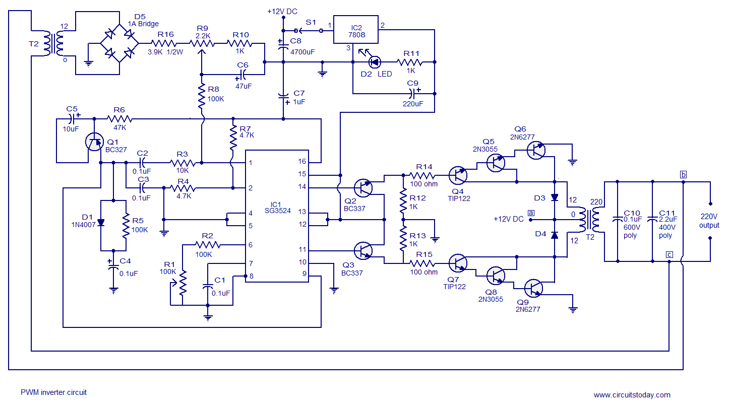
Pin On Circuit Diagram View the full circuit design tutorial. It can be used in dc to dc converter circuits. TL494 inverter Heres a classic inverter circuit built around the IC TL494.


 0 kommentar(er)
